Construction
The standard slip lining procedure is normally a seven-step process. While the actual number of steps may vary to some degree in the field, the procedure remains the same for all practical purposes. The procedures for rehabilitation of gravity and positive pressure pipelines are essentially the same. Some subtle differences become apparent in the manner by which some of the basic steps are implemented. The seven basic steps are described below. Additional details are provided in Chapter 11 of the Plastic Pipe Institute (PPI) Handbook of Polyethylene Pipe.
-
Inspect the existing pipe.
The first step for a slip lining project is the inspection of the existing pipe, which determines the condition of the line and the feasibility of the insertion renewal. The number and the locations of offset pipe segments and other potential internal obstructions are identified, typically by use of a remote controlled closed circuit television camera. As the unit is pulled or floated through the original pipe, the pictures can be viewed and recorded with on-site television recording equipment.
-
Clean and clear the line.
Cleaning is accomplished using cleaning buckets, kites or plugs, or by pulling a test section of polyethylene liner through the existing pipe structure. This step is often undertaken in conjunction with the previous inspection process.
-
Join lengths of polyethylene pipe. Polyethylene pipe
may be joined by butt fusion technology, gasketed bell and spigot joining methods, or by extrusion welding. The specific method to be used will be determined by the type of polyethylene pipe being inserted into the existing pipe structure. Solid wall polyethylene pipe is usually joined using butt fusion techniques. Polyethylene profile walled pipe, on the other hand, can be joined by integral gasketed bell and spigot joining methods or, preferably, by the extrusion welding technique.
-
Access the original line.
Excavation of the access pits is the next step in the insertion renewal procedure. Access pits will vary considerably in size and configuration, depending on a number of project-related factors such as:
- Depth of the existing pipe
- Diameters of the liner and the existing pipe
- Stiffness of liner pipe
- Prevailing soil conditions
- Equipment availability
- Traffic and service requirements
- Job site geography
For example, a fairly large access pit may be required when attempting to slip line a large diameter system that is buried deep in relatively unstable soil, in comparison to the more prevalent situation of a small required pit, possibly only slightly wider than the liner itself, for a smaller diameter pipeline that is buried reasonably shallow (5 to 8 feet).
-
Installation of the liner.
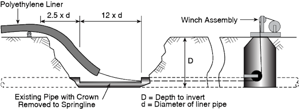
Insertion of the polyethylene liner may be accomplished by several techniques. Prefused or welded lengths of solid wall polyethylene pipe may be "pulled" into place. Gasket-jointed profile pipe, on the other hand, must be installed by the push method to maintain a water-tight seal.
Prefused or welded lengths of polyethylene liner may be pulled into the existing pipe using a cable and winch arrangement. However, this method may not be entirely satisfactory when the load requires an unusually large downstream winch, such as when attempting to install a large-diameter heavy-walled polyethylene pipe and/or a long segment length. When the pull technique is not practical, the push technique may be a viable solution.
The push technique uses a choker strap, placed around the liner at a workable distance from the access point. A track-hoe, backhoe, or other piece of mechanical equipment pulls the choker to push the liner through the existing pipe. The process may be assisted by having a front-end loader or bulldozer simultaneously push on the trailing end of the liner segment. The installation of gasketed profile PE pipe, if appropriate for the application, requires the use of the push technique in order to keep the joints from separating, as well as to position the liner. This process inserts the liner without the necessity for having a high capacity winch and cable system.
The pushing and pulling techniques can sometimes be combined to provide the most efficient installation method. Typically, this arrangement can be used when attempting the placement of unusually heavy walled or long lengths of polyethylene liner.
-
Make service and lateral connections.
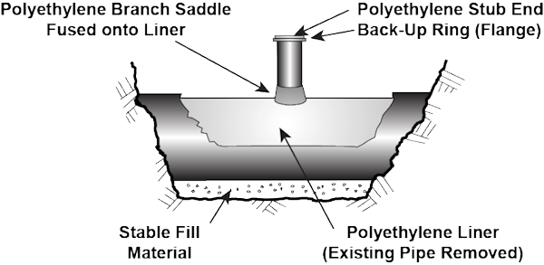
After the recommended 24-hour relaxation period following the insertion of the polyethylene liner, each individual service connection and lateral can be added to the new system. One common method of making these connections involves the use of a wrap-around service saddle. The saddle is placed over a hole that has been cut through the liner and the entire saddle and gasket assembly is then fastened into place with stainless steel bands. Additional joint integrity can be obtained by extrusion welding of the lap joint created between the saddle base and the liner. The service lateral can then be connected into the saddle, using a readily available flexible coupling. Once the lateral has been connected, following standard direct burial procedures can stabilize the entire area. For pressure applications, lateral connections can be made using sidewall fusion of branch saddles onto the liner. As an alternate, a molded or fabricated tee may be fused or flanged into the liner at the point where the lateral connection is required. Mechanical fittings are also a viable option; see Chapter 9 of the Plastic Pipe Institute (PPI) Handbook of Polyethylene Pipe.
-
Make terminal connections and stabilize the annular space.
Pressurized pipe systems will require connection of the liner to the various system appurtenances. These terminal connections can be made readily through the use of pressure-rated polyethylene fittings and flanges with fusion technology. All of these require stabilization of the transition region to prevent point loading of the liner. Mechanical joint adapters can be used; see Chapter 9 of the Plastic Pipe Institute (PPI) Handbook of Polyethylene Pipe.
Gravity lines do not typically require pressure-capable connections to the other system appurtenances. In these situations, the annular space will be sealed to prevent migration of ground water along the annulus and, ultimately, infiltration through the manhole or headwall connection.